
MC-V12 Platform Overview
A decentralized mesh communications platform by James E. Smith LLC, built to deliver voice and data without reliance on cellular or Wi-Fi infrastructure.
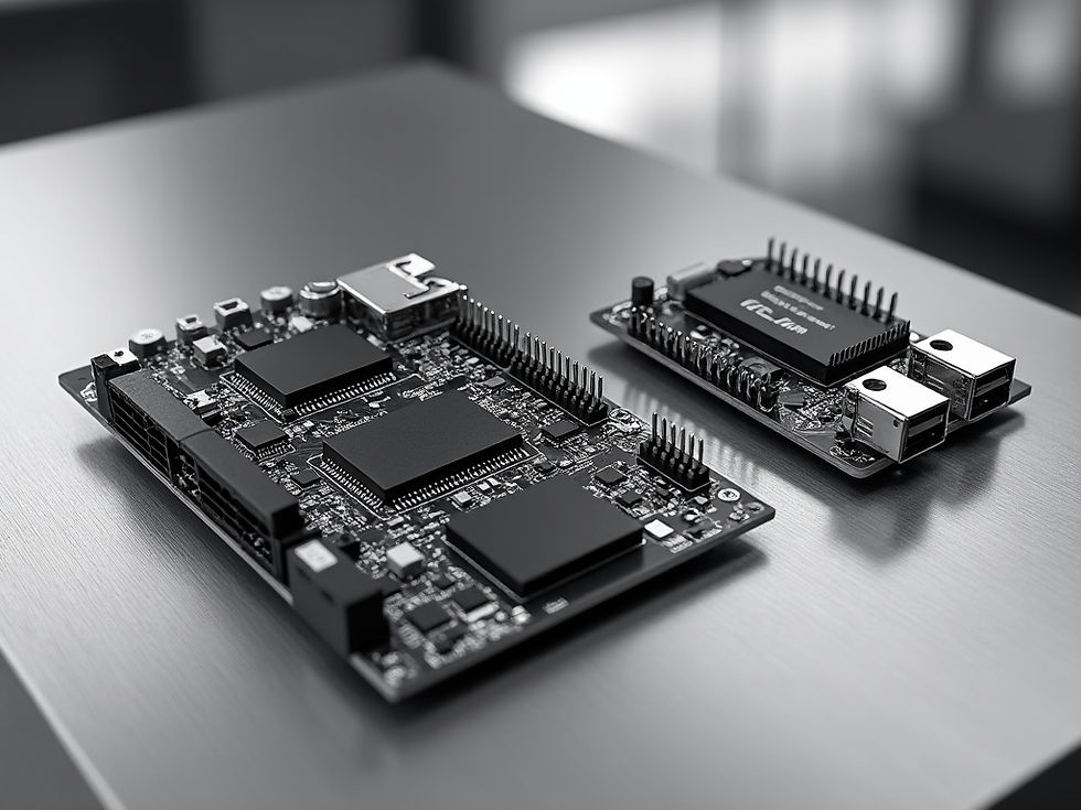
Hardware-Agnostic SBC/SDR Platform
The platform pairs single-board computers (SBC) with software-defined radios (SDR) in a hardware-agnostic architecture, allowing nodes to be built from interchangeable components rather than a single proprietary device. Each node operates as an independent peer, supporting a decentralized mesh with no central point of control or failure.
Encryption & Decoupling
Encryption is user-controlled: keys are held and managed by the operator, not by a vendor or central service. Decoupling the security layer from the underlying hardware keeps control of communications with the user, regardless of which SBC or SDR components are deployed.
JAMES E. SMITH LLC — MC-V12 | CAPABILITIES OVERVIEW
What the software supports
Voice and messaging
Two-way voice and text communication over supported RF or IP links.
Images
Image transfers and live image streaming between connected devices.
Radio over IP
Interconnection through Ethernet, Wi-Fi, and suitable fiber-backed IP networks.
Monitoring and security
Communication status, device controls, network activity, and supported encryption features.
Direct RF communications do not require commercial Internet infrastructure when appropriately authorized transmission hardware is used. RoIP provides a separate path over available IP networks.
The operating software is real; the range and network-area scenarios on the following pages remain preliminary engineering estimates.
Illustrative RF range scenarios - not verified MC-V12 field results
Range Estimates & Scaling
Node-to-node range depends on terrain, antenna height, line of sight and RF interference. The figures below are planning estimates only and must be validated through an on-site survey.
Estimated Range by Terrain
Terrain: Open desert / clear line of sight.
Typical Range: Longest range (site-dependent).
Terrain: Rural / rolling hills.
Typical Range: Moderate range.
Terrain: Suburban / light foliage.
Typical Range: Reduced range.
Terrain: Dense urban / indoor.
Typical Range: Shortest range.
Estimates are indicative only and not a performance guarantee.
⌗
Network Scaling
Coverage extends by adding nodes. Each node relays traffic for its neighbors, so the mesh grows outward without central infrastructure.
- Add relay nodes to bridge terrain gaps
- Elevate antennas to improve line of sight
- Plan node density around expected traffic
- Validate coverage with a site survey
Urban Range and Repeater Networks
Buildings, street canyons, vehicle movement, and interference can interrupt direct links. Properly placed rooftop stations may improve outdoor connectivity by offering clearer radio paths.
Illustrative urban link ranges
Example conditions: operation near 900 MHz, compatible receivers, suitable outdoor antennas, and transmit power at both link endpoints.
RF output: 0.1 watt
Moving vehicle to vehicle: 0.1-0.35 mi
Vehicle to rooftop station: 0.25-0.75 mi
Rooftop to rooftop: Not modeled
RF output: 1 watt
Moving vehicle to vehicle: 0.2-0.7 mi
Vehicle to rooftop station: 0.5-1.5 mi
Rooftop to rooftop: 1-3 mi
RF output: 5 watts*
Moving vehicle to vehicle: 0.3-1.1 mi
Vehicle to rooftop station: 0.8-2.4 mi
Rooftop to rooftop: 1.5-5 mi
*The 5-watt example assumes appropriate regulatory authorization for the selected frequency, emissions, and equipment. It is not a default unlicensed Part 15 option.
Illustrative outdoor geographic reach
With interconnected rooftop repeaters, suppose each station has an effective 0.5-1 mile outdoor radius and the footprints overlap by roughly 25-35%. The resulting gross geographic areas would be:
Interconnected rooftop repeaters — Potential outdoor area
4 stations — About 2-9 square miles
5 stations — About 2.5-12 square miles
6 stations — About 3-14 square miles
Connection stability: Fixed rooftop links with clear visibility are generally more consistent than moving street-level connections. A vehicle may lose signal behind buildings, in tunnels, or between coverage areas. Overlapping repeater footprints can help, but do not guarantee continuous service.
These square-mile figures are geometric planning illustrations, not continuous service areas or measured MC-V12 performance. Building shadows and interference can create substantial gaps.
RoIP and customer-provided fiber
Compatible stations may use high-speed fiber or other IP transport to exchange communications traffic even when there is no direct RF path between their rooftops. Their individual radio footprints can be distributed across a much wider city or region. IP-connected services depend on the transport network remaining available.
Line-of-Sight Planning Ranges
With little obstruction, properly positioned antennas may support longer connections than in dense urban environments. The following numbers are illustrative rather than tested product specifications.
Illustrative clear line-of-sight ranges
RF output: 0.1 watt
Vehicle to vehicle: 0.5-2 mi
Vehicle to 100-ft station: 1.5-4 mi
Elevated fixed link: 3-8 mi
RF output: 1 watt
Vehicle to vehicle: 1-3 mi
Vehicle to 100-ft station: 3-8 mi
Elevated fixed link: 10-25 mi
RF output: 5 watts*
Vehicle to vehicle: 2-5 mi
Vehicle to 100-ft station: 5-12 mi
Elevated fixed link: 15-35 mi
Assumptions: operation near 900 MHz; outdoor vehicle antennas; an elevated repeater around 100 feet above local terrain; and high-ground or tower sites with suitable directional antennas for long fixed links. Terrain curvature, Fresnel-zone clearance, antenna gain, receiver sensitivity, noise, and supported data rate can all change the result.
Stability: Fixed clear-line-of-sight connections typically offer the most predictable reception. Moving vehicles may still encounter temporary fading. No uptime percentage or distance-specific image-streaming performance is claimed without field measurements.
Compliance & Regulatory Notes
Radio Frequency Use
Operation of the system must conform to the radio frequency, power and licensing rules applicable in the jurisdiction of deployment. Configuration is the responsibility of the operator.
Range Estimates
All range figures are estimates. Actual performance varies with terrain, obstructions, weather, antenna configuration and interference, and is not guaranteed.
Technical Disclaimer
Information in this overview is provided for general reference and may change without notice. It does not constitute a warranty or legal advice.
Operational Safety
Deployments should follow applicable safety, data protection and operational standards. Contact James E. Smith LLC to review requirements for your specific use case.
User-supplied hardware and legal operation
MC-V12 supports receive-only operation as well as transmission configurations using compatible, appropriately authorized equipment. In the United States, certain digitally modulated systems in 902-928 MHz may qualify for unlicensed operation up to 1 watt conducted power under FCC Part 15, subject to antenna, emission, and equipment requirements. A generic SDR plus amplifier is not automatically compliant. Five-watt transmission requires a lawful operating basis for the selected setup.
Available product and continuing enhancements
MC-V12 is operational software. James E. Smith LLC continues advancing supported configurations, hardware compatibility, and network applications. Customers can explore direct RF connections, receive-only systems, IP-based communication, and distributed station architectures using suitable equipment.
Request Technical Evaluation
Contact James E. Smith LLC to discuss MC-V12 capabilities, evaluation requests, and technical consulting. Specifications and range estimates are subject to technical review and applicable compliance requirements.